HRSR - Heat Recovery Silencer Radial Cogeneration Series
Fully Packaged for Micro-Cogen Applications Through the Large Turbines.
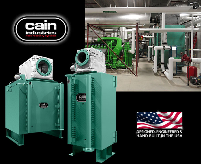
The HRS Radial waste heat recovery silencer is a module configuration package with 176 standard models available. It packages standard features such as: full exhaust bypass, full heating surface access, factory insulation, hard shell exterior, stainless interior, 3" thickness factory insulation, and a variety of finned tube types and fin spacings to fit the proper application. The HRSR is designed to receive the total exhaust and liquid flow from a single source and control exit temperatures to the desired performance levels. During full operation, the radial design channels the exhaust flow through an hour glass expansion flow pattern which provides for significant dBA reduction.
The full port exhaust bypass is located at the top for convenient installation. Depending on space considerations, the unit may be installed in the horizontal position as shown below. The unique configuration of the single row design heating surface allows for reduced fouling potential. The full access to the core with optional hinged doors also allows for fast routine inspection and/or manual cleaning. Finned tube replacement requires no overhead cranes, special rigging, special crews, or extra roof height above the unit. Individual finned tube replacement, if required, is fast and easy with minimum downtime.
Engine Exhaust Application
Capacity: 200kW to 7MW
Entering gas temps: up to 1,250°F
Heat Sink Types: engine jacket water, process water, boiler water, or ethylene glycol
Features
|
Optional Equipment
|
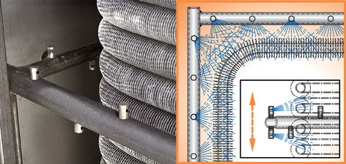
Timed Automatic Sootblower (optional)
The exclusive Cain Industries Timed Automatic Sootblower design is applied to combustion sources where the sulfur content is high and/or combustion efficiency is poor. When a soot layer accumulates on the heating surface to a thickness of 1/8", fuel consumption is increased by 8.5%. The sootblower is also applied when it is not cost-effective to open inspection doors and clean the exchanger by other means. The sootblower system will continually keep the heating surface at a high performance level and eliminate the day-to-day operator expense and engine down time.
The blowdown sequence occurs while the engine is in full operation and is fully adjustable. The special flood-jet type nozzles achieve maximum cleaning velocity using steam or air as discharged through an electric control valve (included). Together they form a "continuous knife edge concentrated spray pattern" surrounding the heating surface. This "ring nozzle assembly" as attached to a manifolded flexible steel hose assembly, is powered up and down by a pneumatic drive cylinder. Dual timing relays allow complete control for 30 second cycle duration and intervals specific to each application. Final results are controlled double cleaning action, insuring that the maximum BTU recovery and anticipated savings are achieved.
Liquid Temperature Control (optional)
Operating Sequence: During a cold startup the exhaust bypass will be powered to the normal operating position. As the liquid temperature rises and approaches a preset point, the exhaust bypass damper will begin to move to the temperature control position. When the desired temperature is completely satisfied the damper actuator will move to the maximum open position, bypassing 99% of the exhaust flow (100% bypass cannot be attained due to some leakage and residual heat in contact with the fin tubing). Included is a 4-20 mA output controller, thermocouple, thermocouple weld and wire, and modulating bypass actuator installed, wired, and tested for a single 120 volt, 1ph, 60hz power connection.